|
TH-2 XPR Support
| |
|
Last updated on: 11-29-19 |
TH-2 XPR Software Support/Downloads
TH-2
XPR Tandem Rotor Helicopter
TH-2 XPR COAX and KMAX/V22
TH-2 XPR Universal 5x8 Mixer
| Using the TH-2 XPR with BeastX FBL
controller |
Download |
Added 7-12-19 |
TH-2 XPR Users Guide
Topic Index
TH-2 Software Installation
(PC side)
Loading Program and Settings (TH-2)
Quick
Setup Guide
Inputs/Outputs Description
Power
Requirements
General
Information
Servo
Drive Capability
RUN LED /
SYS LED
Receiver/Gyro Compatibility
Special
Precautions
Inputs
Connections
Servo
Connections
Run
Mode / Trouble Shooting
Preflight
Checklist
TH-2 Software Installation (PC side)
- The Tech-Link 2.X software must be
installed first. Visit the support page
HERE
- Download the desired TH-2 XPR software
application using the links
above.
- The downloaded software is in a folder
contained in a zip file. The folder will be named TH, CA, UM
etc.
You must copy the unzipped software folder to the folder "Tech-Link
2.X". If an old folder with the same name
already exists you must either rename it or delete it first.
- Follow steps 2 and 3 for each
software application you want to install.
- Tech-Link 2.X can now be used to load
the software and settings and to modify the settings etc.
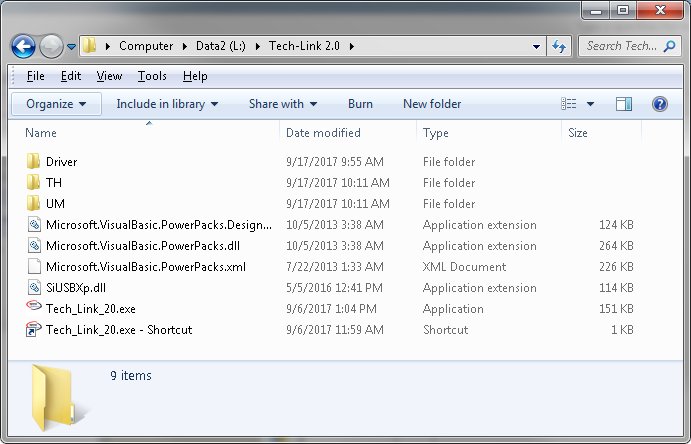
| |
Directory screen shot after the
installation
Shows TH and UM software application folders added
|
|
Loading Program and Settings (TH-2)
The TH-2 software consists of two main
files, the "program" file which has a ".hex" extension and the
"settings" file
which has a ".cst" extension, these two files must be loaded
before using the TH-2 in your application.
You can create new settings files by modifying and saving with a
different name. You can even share settings
files with others.
Loading a Program file
Be sure external power is removed and connect the TH-2 XPR to
the PC with the USB cable.
This will put the unit into Program mode.
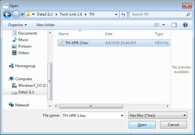
Run Tech-Link, Click LOAD under the Program menu, browse to the
desired software folder i.e. TH, CA, UM etc. and
select the desired hex file.
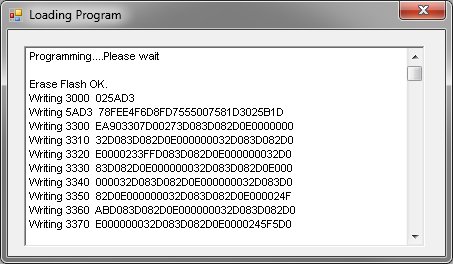
In this example, the tandem software
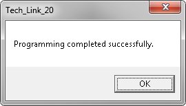
TH-XPR-2.hex is selected. Click Open, wait until the "Programming
completed successfully"
window appears. Close the windows.
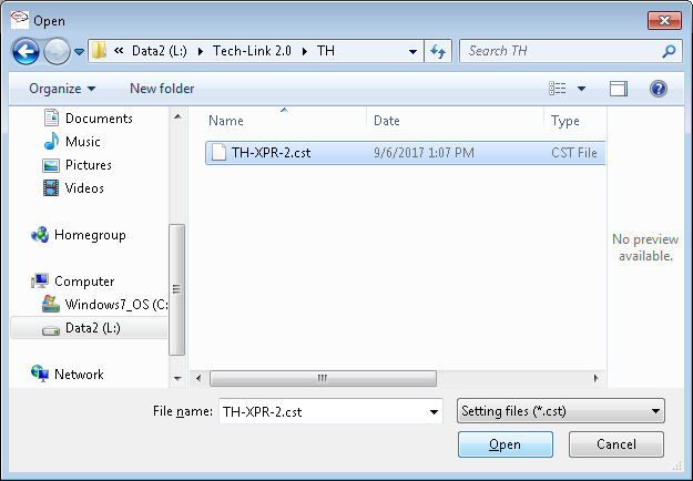
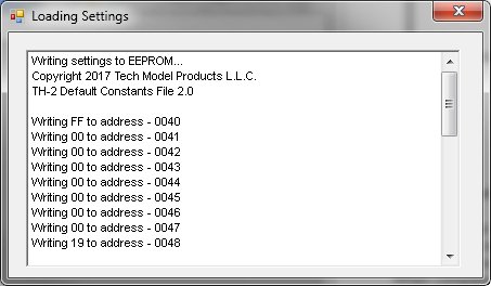
Loading a Settings file
Click LOAD under the Settings menu, browse
to the proper software folder i.e. TH, CA, UM etc. and
select the desired settings file. Note: Choose the same folder that you
used for the program load.
In this example, the tandem settings
TH-XPR-2.cst is selected. Click Open, wait until the "Load completed
successfully"
window appears. Close the windows.
Quick Setup Guide
- Load the Program file i.e. Tandem, Coax,
Universal etc.
- Load the Settings file, stock or
customized.
- Connect the TH-2 XPR to your application
- Connect inputs, outputs and power.
- Turn off all swashplate mixing done by
your transmitter.
- If your application has any swashplates
then get the collective pitch function working first.
Adjust the servo reversing settings (TH-2) to get all servos moving in
the same direction.
If needed, reverse the function direction (stick movement) by reversing
it in the transmitter.
-
Go through each control function
and check for proper stick direction and change the
reversing in the transmitter as needed. Adjust the servo centering
settings as needed (TH-2).
-
Assign the desired gain settings
to the external gain controls PT1..PT4 and X.
-
Setup program mixes in your
transmitter based on your application. For example, DCP (tandem)
would be a program mix of elevator master and CH5 slave.
-
Double check the directions on
any external gyros.
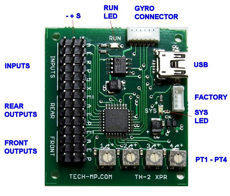
Inputs/Outputs Description
The following table describes the TH-2
XPR inputs/outputs and indicators:
| |
Name |
Type |
Description |
|
|
|
|
|
|
|
A - Aileron |
input |
Aileron input from Rx
or gyro |
|
|
E - Elevator |
input |
Elevator input from Rx
or gyro |
|
|
R - Rudder |
input |
Rudder input from Rx or
gyro |
|
|
P - Pitch |
input |
Pitch input from Rx
(Note: A gyro must not be used on this input depending on
the application that is running. Refer to the apps
specifications.) |
|
| |
5 - CH5 |
input |
CH5 input from Rx or
gyro |
|
|
X |
input |
External input for adjusting
gains/settings from Rx - Allows control from spare channel - User
assignable |
|
|
Rear outputs |
outputs |
Rear servo outputs Ep,
A, E, P |
|
|
Front outputs |
outputs |
Front servo outputs Ep,
A, E, P |
|
|
Gyro |
I/O |
External gyro sensor
connector |
|
|
USB |
I/O |
USB "Mini-B" type jack
(5 pin) for connection to a PC |
|
|
RUN LED (red) |
Indicator |
Blinks when mixer is
running - See below |
|
|
SYS LED (yellow) |
Indicator |
Blinks/solid based on
mode - See below |
|
|
PT1 - PT4 |
inputs |
External inputs for
adjusting gains/settings etc. - User assignable |
|
|
- + S |
power/signal |
Main power bus and
signals header - External power input |
|
Inputs/Outputs Diagram
Power Requirements
The TH-2 requires a 5 volt power source. It
must be maintained between 4.9 and 5.5 volts.
Do
not exceed 5.6 volts since it can damage the unit.
A 5V or 5.5V BEC with a battery large
enough to supply the power is recommended.
Care must be used when choosing the power source since it must be
capable of driving the intended load. The TH-2 itself uses
very
little power so you need to determine how much current is required
by all of the components in your model.
This would include components such as:
- Receiver
- Gyros
- Servos
- Accessories
Many of the Electronic Speed Controllers
(ESC) on the market have a BEC which can only supply 1 amp of
current. This would be insufficient in a
model setup that has a receiver, 6 micro servos, and 2 gyros.
A BEC with 3 to 5 amps capacity would be needed.
For large or digital servos you will
need to use extender boards or similar, which allow you to
route power directly to the servos bypassing the TH-2.
The TH-2 in this case, only drives the servo input signals which are
low power.
General Information
- The USB cable must be plugged into an
un-powered TH-2 to initially connect with Tech-Link.
This puts the unit into Program Mode.
Power is supplied by the USB cable.
No damage will occur if you forget to remove power first. It just
won't connect, and and error message will be displayed.
- Unconnected inputs - The TH-2 will
initialize the input values to neutral (1500 us) for the A,E,R,5,P
inputs and will
initialize the X input to the minimum value of 1000 us. If an
input is first connected then disconnected, then the input
value will stay set to the last value it was when disconnected.
- TX type, servo type, servo layout, and
servo arm position will determine the servo reversing settings needed in
the TX and TH-2.
- For some applications, the TH-2
synchronizes with the pitch channel (CH-6 on most radios) and expects it
to be the last pulse
(that it "sees") in the data frame sent by the transmitter.
A gyro should not be used on this channel. Check the
specifications
for the application for details.
-
The gain settings
also allow you to balance the amount of servo travel from the
contributing channels and
prevents clamping. The TH-2 is set to clamp at 0.90 ms min. and
2.10 ms max. to prevent servo damage
in the event of interference.
-
Once the TH-2 is programmed and setup with your PC, there is no
longer any need to have a PC at your flying field etc.
All adjustments can be done with your transmitter or the five
external gain/setting inputs.
Servo Drive Capability
The TH-2 XPR is designed to drive up to
8 micro servos (HS-50, HS-65MG, etc.) with just the primary power
input. Any more than this
requires the secondary power input or the use of the extender
boards. These limitations are due to the current carrying
capacity of
the connectors. Using the secondary power inputs (even if not
required) provides redundancy and is recommended for safety.
The Servo Drive Table below summarizes the possible combinations of
different servo counts and sizes with the required power inputs.
Servo Drive Table
| |
| Servo Type |
Max Servos |
Primary Power |
Secondary Power
(3) |
Extender |
| Micro |
8 |
Yes |
Optional |
Optional |
| Mini |
8 |
Yes |
Yes
(1) |
Optional |
| Large/Digital |
8 |
Yes |
N/A
(2) |
Yes |
|
|
|
|
Notes:
1: Secondary power is not required when extender boards are used. |
|
2: N/A means Not Applicable. |
|
3: Any unused header power pins can be used as secondary power
inputs. |
RUN LED / SYS LED
The TH-2 XPR has two indicators to show
the current operating status. The table below summarizes this:
| |
| Mode |
RUN LED
(red) |
SYS LED
(yellow) |
| Program |
ON SOLID |
ON SOLID |
| RT |
FLASHING |
FAST FLASHING |
| Run |
FLASHING |
SLOW FLASHING |
|
|
Receiver/Gyro Compatibility
The TH-2 XPR requires a low jitter
receiver/gyro to operate properly. The receiver/gyro should have a
jitter level of about 1 to 2 microseconds or less.
The TH-2 XPR measures the pulse widths from the receiver/gyro
outputs and then performs 32 bit calculations on these measurements
to perform
the mixing. Any receiver or gyro jitter error adds and
subtracts, with mixing, which in some cases doubles or halves
the error.
A typical servo has a deadband of about 8 to 10 microseconds, any
jitter above the deadband will cause the servo to hunt and twitch.
The TH-2 XPR will work with either "Heading Hold" or standard gyros.
We recommend using a Futaba GY240 type gyro.
Other units on the market may perform just as well, we just have not
tested them yet.
The GY401 gyro has been tested and works fine. The gyro should
be set to work in "analog" servo mode.
The FS8 Copilot system has been tested and works fine.
DX9, DX7 and DX6 radios have been tested and
work fine. They output the data just as a PPM receiver does
with a 22ms frame rate.
Note: Some PCM receivers output servo
data "non-sequentially" and may not completely work with the TH-2
XPR.
Special Precautions
- Caution:
The TH-2 XPR does not have any failsafe features. It operates as
a slave device driven by the receiver. Any glitch or interference
passed from
the receiver to the TH-2 XPR will cause the servos to operate
erratically. The TH-2 XPR does provide clamping to the servo
outputs to prevent damage.
- Caution:
It is important that the TH-2
XPR is connected properly before the power (battery) is connected.
Failure to so do may damage the unit and
whatever it is connected to at the time. The TH-2 XPR supports
most radios such as Futaba, JR, Hitec and others without modifications.
- Caution:
Power should be removed or
switched off when making any kind of connections to the TH-2 XPR.
This includes the USB.
- Caution:
The TH-2 XPR assumes a center
positive power pin for the connectors. Some radio equipment such
as Airtronics, uses a center negative
power pin. The appropriate connector adapters must be used in this
case.
Inputs Connections
The TH-2 XPR has 6 inputs that come from
the receiver/gyro. Single 3-wire cables or the "6-input" cable
can be used.
- Aileron input plugs directly into the receiver's Aileron
output or optional
gyro.
The gyro if used, plugs
directly into the
receiver's Aileron output.
- Elevator
input plugs into the receiver or optional gyro.
The gyro if used, plugs directly
into the receiver's Elevator output.
- Rudder input
plugs
into the receiver or optional gyro.
The gyro if used, plugs directly
into the receiver's Rudder output.
- CH5 input
plugs
into the receiver or optional gyro.
The gyro if used, plugs directly
into the receiver's CH5 output.
- Pitch
plugs
into the receiver or optional gyro.
The gyro if used, plugs directly
into the receiver's pitch output.
NOTE: A gyro must not be used on this input for some apps.
Refer to the apps specifications.
- X
input plugs into the receiver
and a gyro should NOT be used here. This input is used as an
external gain or setting control.
Servo Connections
The TH-2 XPR has 8 servo outputs.
The servo connectors can be plugged in directly to the servo outputs
on the main header.
The servo signal wires must be facing the labels A, E, P or Ep.
Connecting the servo connector on backwards will not harm anything.
The servo just won't operate.
When using extender boards and long signal
wires, it may be necessary to use ferrite rings on the signal wires to
prevent glitching.
This will depend on your particular installation.
| |
 |
|
| |
Extender Board |
|
Run Mode / Trouble Shooting
With the radio turned on and following a
power-up, the TH-2 XPR will enter Run mode if the USB is not
connected and
a valid software application was loaded.
The red RUN LED will blink about twice a second indicating that the
unit is operational. If the RUN LED fails to blink
(LED stuck on or stuck off) this indicates a problem exists.
Below is a list of things to check that may be the cause:
- Check that the power
is connected to the main header and the battery is charged.
- Check that
transmitter is on and operating properly.
- Check that receiver
is on and operating properly.
- Check that the
receiver/gyro inputs are connected properly.
- In some
applications, the pitch input must be connected and active.
Preflight Checklist
This checklist at a minimum should be
performed before each flight of the model:
- Inspect the model
for flightworthiness.
- Perform a radio
range check before attempting to fly the model.
- Check that the TH-2
is operational (RUN LED blinking).
- Check the controls.
- Happy flying
Copyright © 2018 by Tech Model
Products LLC. • All Rights Reserved |